Water Vapor Migration & Condensation Control in Buildingsby William G. AckerShare This Article The basics of psychrometric analysis of moisture conditions, including evaluation of vapor barriers and other construction features, and internal and external moisture sources. Examples help guide the discussion of this complex topic. Water vapor is the gaseous form of water and is an invisible source of many problems in today's buildings. This article will provide a basic understanding of how water vapor transport occurs, when it condenses, and when it can cause damage and health problems. Water vapor can travel through building structures by: • Diffusion caused by vapor pressure differentials • Air flow created by temperature differentials • Air flow created by mechanical systems • Rain penetration through intake louvers |
Articles |
|
To begin with, psychrometric
conditions on the inside of a building
are usually different than the
outside conditions. The difference
in psychrometric properties results
in a vapor pressure differential
from inside to outside, which
sets up the driving force for water
vapor diffusion. The direction of
water vapor flow is from high vapor
pressure or high humidity to
low vapor pressure or low humidity.
In colder climates, such as the
northern U.S. and Canada, the
amount of water vapor in the outside
air is very low (low vapor
pressure) and is less than the
building inside air (high vapor pressure). Thus the water vapor
diffusion is from inside to outside.
In warmer climates with short
heating seasons, the water vapor
drive is from outside to inside due
to the drying effect of indoor air
conditioning. If the water vapor
condenses in the wall or roof section
and does not have the opportunity
to dry out, then over a period
of time, there will develop an
accumulation of water that could
cause damage and/or mold
and mildew. Keep in mind
that this is a dynamic situation
where condensation
may occur during part of
the day and evaporation
during another part. The
engineer's job is to design
the cavity so that condensation
does not occur, does
not occur frequently, or
only occurs in a safe region,
such as an air space with
drainage. The terms and equations  for water vapor transmission
or diffusion are listed
in the accompanying sidebar.
Equations 6 and 7 are
the vapor diffusion equations
used to calculate the amount of
water vapor that passes through
the wall or ceiling cavity. The
overall coefficient of vapor transmission,
M, is determined by
adding the resistances to vapor
transmittence for the construction
materials (and air films) and
then taking the inverse of that
summation. This procedure is illustrated
in Equations 4 and 5.
The inside and outside vapor
pressures can be determined from
test data or by using typical psychrometric
data for that region. If
there is concern over the amount
of water vapor diffusion or concern
over condensation in the cavity,
the engineer may need to install
a vapor retarder. for water vapor transmission
or diffusion are listed
in the accompanying sidebar.
Equations 6 and 7 are
the vapor diffusion equations
used to calculate the amount of
water vapor that passes through
the wall or ceiling cavity. The
overall coefficient of vapor transmission,
M, is determined by
adding the resistances to vapor
transmittence for the construction
materials (and air films) and
then taking the inverse of that
summation. This procedure is illustrated
in Equations 4 and 5.
The inside and outside vapor
pressures can be determined from
test data or by using typical psychrometric
data for that region. If
there is concern over the amount
of water vapor diffusion or concern
over condensation in the cavity,
the engineer may need to install
a vapor retarder.The ASTM definition of a vapor retarder is a material with a vapor performance (PERM) of 1.0 or less. The resistance to vapor transmittance is illustrated in Equation 1. The resistance to vapor transmittance is the inverse of the PERM value; therefore, the lower the PERM value, the greater the resistance to water vapor diffusion. Some state codes require a PERM rating of less than 1.0 to qualify as a vapor retarder. Water Vapor DiffusionWater vapor diffuses through many building materials other than metals when a vapor pressure difference exists across the construction. One consensus that seems to have been reached is that vapor retarders are needed in cavity walls and ceilings. In cold and moderate climates, the vapor retarder is placed on the indoor side of the cavity. This is because the water vapor flow is from inside to outside (the inside is the higher vapor pressure).  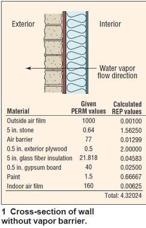 In some warm climates
that have a short heating
season, the vapor retarder is
placed on the outside of the cavity
because air conditioning of the indoor
air dries the air, thus lowering
the indoor vapor pressure below
the outdoor vapor pressure. In
some warm climates, vapor retarders
are installed on both theindoor and outdoor sides of the cavities.
Some typical vapor retarder
materials are listed in Table 1. In some warm climates
that have a short heating
season, the vapor retarder is
placed on the outside of the cavity
because air conditioning of the indoor
air dries the air, thus lowering
the indoor vapor pressure below
the outdoor vapor pressure. In
some warm climates, vapor retarders
are installed on both theindoor and outdoor sides of the cavities.
Some typical vapor retarder
materials are listed in Table 1.To calculate the amount of water vapor diffusion, the engineer must define the design indoor and outdoor psychrometrics to obtain the needed vapor pressures. If the analysis involves an existing facility, the engineer can test the actual conditions. The properties that must be determined are barometric pressure, gauge pressure, dry bulb temperature, and something to identify moisture in the air, such as wet bulb temperature, dew point temperature, or relative humidity. These properties and the equations to calculate the vapor pressure are illustrated in the accompanying sidebar. 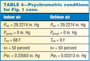 Relative humidity, RH, is a very
misunderstood term. It describes
the amount of moisture the air
holds relative to the maximum
it can hold at that temperature.
If, for example, the air temperature
is 70 F and the
relative humidity is, say 50
percent, the air at that temperature
contains only 50
percent of the moisture it is
capable of holding. If the
temperature then drops
from 70 to 52 F, the relative
humidity increases to 94.8
percent even though the
amount of moisture in theair
remained unchanged. The reason
is that cold air cannot hold as
much moisture as warm air. In
both cases, however, the absolute
humidity, W (lb water vapor/lb
dry air), is the same. Relative humidity, RH, is a very
misunderstood term. It describes
the amount of moisture the air
holds relative to the maximum
it can hold at that temperature.
If, for example, the air temperature
is 70 F and the
relative humidity is, say 50
percent, the air at that temperature
contains only 50
percent of the moisture it is
capable of holding. If the
temperature then drops
from 70 to 52 F, the relative
humidity increases to 94.8
percent even though the
amount of moisture in theair
remained unchanged. The reason
is that cold air cannot hold as
much moisture as warm air. In
both cases, however, the absolute
humidity, W (lb water vapor/lb
dry air), is the same.To summarize, a change in the air dry bulb temperature will cause a shift in the relative humidity even though the amount of moisture in the air remains unchanged. A psychrometric computer analysis of these two conditions are illustrated in Tables 2 and 3. You will also note that the dew point temperature is the same in both cases, which supports the theory that the moisture in the air did not change. Also, you will note that the vapor pressure is the same in both cases. The vapor pressure, Pw (partial pressure of water vapor in the mixture), of the outdoor and indoor air can be calculated by using the equations in the sidebar and by using the steam tables to obtain the pressure of saturated pure water, Pws. Using the 70 F/50 percent RH condition (Table 2), we will calculate the vapor pressure of air. Given: • TDB = 70 F • Pbar = 29.921 in. Hg • Pgauge = 0 in. Hg • Pabs = 29.921 in. Hg Calculations: • Pws = 0.7369 in. Hg (from steam tables) • RH = 50 percent = Pw/Pws • Pw = 0.3684 in. Hg The following example will illustrate how to calculate the amount of water vapor diffusion through the wall section and will be used to illustrate the importance of a vapor barrier in this case. The diagram in Fig. 1 is a typical 2 by 6 in. wall section. The materials of construction and air films are shown with their PERM and REP values. You will note that this wall does not have an indoor vapor retarder. Psychrometric conditions for this analysis are shown in Table 4. Using this information and the summation of the REP values in Fig. 1, we can calculate the amount of water vapor flow: W = (1/4.32024) 3 (0.23563 – 0.03313) = 0.04687   The diffusion of water vapor through this wall is 0.04687 grains of water vapor per hr per sq ft of wall surface. Now let's determine what happens if we add a 4 mil vapor barrier between the gypsum board and glass fiber insulation. A 4 mil polyethylene vapor barrier has a PERM of 0.08 or a REP of 12.5. This increases the REP summation to 16.82024. Now let's recalculate the amount of water vapor diffusion through the cavity: W = (1/16.82024 3 (0.23563 – 0.03313) = 0.012039 You can see that without the vapor barrier, the amount of water vapor diffusion through the cavity is 3.89 times higher or, in other words, 289 percent higher than the wall with the vapor retarder. This is a significant change, but is it needed? To answer this question, we put the parameters into a computer program that calculates the surface temperatures of all the materials and also calculates the surface dew points to check for condensation. If condensation occurs,  the program prints out stars
next to the calculated surface dew
point temperatures. Table 5
shows the results of the computer
analysis for the wall without the
vapor barrier, and Table 6 is with
a vapor barrier. Without the vapor
barrier, you can see that condensation
does exist. Since water
vapor is moving from inside to
outside, you can see that it starts
at the glass fiber insulation. The
condensation may stop at the
glass fiber insulation due to the
reduction of vapor flow through
the remaining materials. If, however,
the condensation is frequent,
it could cause a loss of insulating
value (R-value), which
could cause the condensation to
move into the adjacent materials.
The wall with the vapor barrier
(Table 6) has no condensation. the program prints out stars
next to the calculated surface dew
point temperatures. Table 5
shows the results of the computer
analysis for the wall without the
vapor barrier, and Table 6 is with
a vapor barrier. Without the vapor
barrier, you can see that condensation
does exist. Since water
vapor is moving from inside to
outside, you can see that it starts
at the glass fiber insulation. The
condensation may stop at the
glass fiber insulation due to the
reduction of vapor flow through
the remaining materials. If, however,
the condensation is frequent,
it could cause a loss of insulating
value (R-value), which
could cause the condensation to
move into the adjacent materials.
The wall with the vapor barrier
(Table 6) has no condensation.
Example CasesFreezer and cold storage facilities require a lot of attention to design details. The indoor vapor pressures can be as low as 0.011 in. Hg, resulting in vapor pressure differentials as high as 0.78 in. Hg, which is three to four times higher than the differentials experienced in residential and commercial buildings. Vapor retarders are critical to reduce the moisture drive into the freezer and to prevent condensation. One client had major condensation problems from the underside of a supermarket floor. The supermarket was built with parking at ground level; the cold freezer facilities and supermarket were on the second floor above the parking area. The parking area is totally open to the outdoor environment. One area that had condensation problems was the underside of a walk-in cooler floor. An elevation sketch of the construction is shown in Fig. 2.The problem was condensation in the false ceiling air cavity. The glass fiber insulation shown on top of the false ceiling would get so wet with moisture it would collapse the false ceiling into the parking area. Surface temperatures based on heat loss calculations are also illustrated in Fig. 2. From these temperatures, you can see that during the summer, the glass fiber insulation was preventing heat gain into the air space. This is a problem because the surface temperatures are well below the outside air dew point temperature. With no vapor barrier and the poor air tightness of the false ceiling, the air cavity will have a dew point very close to the outside air dew point. This, in turn, results in condensation because the vapor can touch a surface that is below its dew point. One solution might be to remove the glass fiber insulation. In this case, however, it is not possible because the air cavity must be heated in winter to prevent freezing of the pipes in the air space. This is why the diagram shows radiant heat pipes. The solution used was to run the radiant heat system in the summer, which raises the surface temperatures above the dew point temperature. To save energy, one could install sensors to monitor the metal deck temperature and the dew point temperature. A controller could then turn on the radiant heat to maintain the surface at 5 F higher than the dew point temperature. The computer condensation analysis program revealed condensation problems inside the false ceiling. One industry that has many problems with water vapor diffusion and condensation is the paper industry. The wet end section of a paper machine takes the water and fiber and forms it into a sheet. The stock temperature is around 100 to 120 F; therefore, the evaporation rate into the building is high. The dry end section, unlike the wet end section, has a hood to capture the water evaporated and discharges the water vapor outside. Some of these hoods, however, have leaks that can raise the humidity excessively inside the building. The molecular weight of water vapor is less than the molecular weight of dry air. Therefore, the water vapor rises to the underside of the paper machine building roof, thus raising the dew point at the underside higher than the rest of the building. At one mill location, the air properties taken at the underside of the roof were as follows: Pbar = 29.8220 in. Hg TDB = 111 F TWB = 103.33 F TDP = 102.05 F RH = 77 percent Pw = 2.0553 in. Hg This particular machine room had little dryer hood leakage. Another survey for a machine room housing five paper machines showed a lot of condensation, corrosion, and spalling of concrete from the roof deck. A mass air and water vapor survey of the building revealed a water vapor flow into the building of 123,175 lb per hr or 248 gpm. As you can imagine, this raised the building humidity to extreme levels. The worst area tested—at the underside of the roof—is illustrated below: Pbar = 29.8220 in. Hg TDB = 159 F TWB = 136.51 F TDP = 135 F RH = 54.81 percent Pw = 5.1651 in. Hg The vapor pressure differential across the roof system in this case is over 4.0 in. Hg, which is tremendous as well as unacceptable. The theory behind preventing roof surface condensation is to keep the inside roof surface temperature above the dew point temperature of the vapor rising to the ceiling. The surrounding air dry bulb temperature heats the roof surface, but due to heat loss through the roof, the surface temperature will always be lower than the dry bulb temperature. One method of raising the roof surface temperature is to add insulation to the roof. If you look back to the first paper mill example, you can see that the dew point is 102 F and the dry bulb is 111 F. Therefore, in this case, you can expect the roof temperature to be less than 111 F but hopefully not at or below 102 F. To help prevent condensation in today's machine rooms, one should supply a roof heating system for the underside of the building roof. Roof heating systems are air handling units that take indoor building air, heat it to 120 F, and distribute it to the underside of the building roof. Depending upon roof insulation levels, this process will then heat the roof to around 110 to 115 F. Certainly, the building does not need any more heat, but it is required until the industry puts a hood on the wet end section. If you look back at the five paper machine building example, you will note that the dew point was at 135 F, which is well above the temperature of the existing roof heating system. In this case, the roof heating system does not prevent condensation. The cure to the condensation problem is to find the hood leaks and patch them. The problems with water vapor condensation inside the machine rooms are complex and require further review. The water vapor transmission is tremendous due to the high vapor pressure differentials. The next problem is to design the roof system so that the vapor can escape without condensation or to have the vapor condense in a safe region. Over 45 percent of the roof failures are caused by poor roof design. Vapor retarders are a necessity.  An example of a paper machine
building roof is illustrated in Fig.
3. The psychrometric test conditions
at the underside of the building
roof were illustrated in the
first example. This mill was experiencing
condensation and concrete
deck spalling. The design
conditions were put into the condensation analysis program to
check for problems. The results
can be found in Table 7.
The program shows condensation
in the concrete roof deck. This
explains the roof spalling problems.
In this case, there was insufficient
insulation in the roof,
resulting in a low inside roof surface
temperature. The steel reinforcement
in pre-cast concrete
decks will corrode when exposed to condensation and chemicals
such as chlorine. Test samples
taken from concrete decks have
shown acid-soluble chlorine-ion
contents of between 100 and 1100
ppm of concrete. Special precautions
need to be taken to prevent
the corrosion of steel reinforcement. An example of a paper machine
building roof is illustrated in Fig.
3. The psychrometric test conditions
at the underside of the building
roof were illustrated in the
first example. This mill was experiencing
condensation and concrete
deck spalling. The design
conditions were put into the condensation analysis program to
check for problems. The results
can be found in Table 7.
The program shows condensation
in the concrete roof deck. This
explains the roof spalling problems.
In this case, there was insufficient
insulation in the roof,
resulting in a low inside roof surface
temperature. The steel reinforcement
in pre-cast concrete
decks will corrode when exposed to condensation and chemicals
such as chlorine. Test samples
taken from concrete decks have
shown acid-soluble chlorine-ion
contents of between 100 and 1100
ppm of concrete. Special precautions
need to be taken to prevent
the corrosion of steel reinforcement.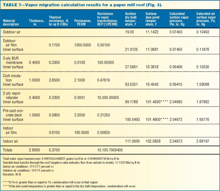  Poor conditions at the underside
of a paper machine building
roof should not be taken lightly.
High humidities will result in
premature failure of the roof support
steel, concrete deck, and
roofing materials. Some mills
have experienced complete failures
just a few years after installation,
and others have had roof
sections fall into the paper machines.
To give you an idea of the
costs, a mill in the south had to
replace the roof steel, concrete
deck, and roofing materials at a
cost of over $1,000,000 or about
$50 per sq ft of roof. The building
housed a tissue machine, and the
replacement occurred 24 years after
installation. Poor conditions at the underside
of a paper machine building
roof should not be taken lightly.
High humidities will result in
premature failure of the roof support
steel, concrete deck, and
roofing materials. Some mills
have experienced complete failures
just a few years after installation,
and others have had roof
sections fall into the paper machines.
To give you an idea of the
costs, a mill in the south had to
replace the roof steel, concrete
deck, and roofing materials at a
cost of over $1,000,000 or about
$50 per sq ft of roof. The building
housed a tissue machine, and the
replacement occurred 24 years after
installation.The last example will illustrate blower door surveys, infrared surveys, the use of mass dry air and water vapor analysis, and adiabatic mixing to solve condensation problems in buildings. It was kept simple so that the analysis would fit into this article. The building is a residential home with severe attic condensation problems in the winter. The home has cathedral ceilings of tongueand- groove maple panels. The home had condensation in the attic that dripped through the ceiling. The contractor told the homeowner that the problem was the storage of 22 face cords of firewood in the basement. The first test conducted was a blower door test to determine the building air change rate. The blower door air flow was 5200 cfm at a differential pressure of 50 pascals (0.201 in. WG). The calculated air change rate in air changes per hour (ACH) is as follows: ACH = (acfm 3 60 min per hr)/(Building volume, cu ft/1 air change) = (5200 3 60)/(21,693/1) = 14.4 This is a high air change rate for a new home. The next step was to determine where the air flow paths were. An infrared-image heat-loss scan was conducted with the blower on and with the blower door off to help accentuate the areas with air flow heat loss. The infrared-image scans showed air flow leaking through the tongue-andgroove ceiling panels. It was discovered later that the kraft-back vapor barrier was not stapled against the inside face of the cathedral ceiling rafters. Instead, the vapor retarder was stapled to the inner sides of the rafters. If the vapor retarder is installed against the inside face of the rafter and the tongue-and-groove paneling is nailed against the vapor retarder, you can achieve air tightness. This was not done. Without air tightness, you have a potentially dangerous situation because air flow can carry much more moisture into the attic than diffusion through the materials. The amount of water vapor diffusion through 1364 sq ft of ceiling in this case is 0.01438 lb of water vapor per hr. The blower door air flow of 5200 cfm was converted to air flow at normal building differential pressure of 3 pascals (0.012 in. WG), which is 1270 acfm. If all of this air flow travels through the tongue-and-groove ceiling into the attic, the water vapor it carries will be 23.70 lb per hr if the home is maintained at 68 F/35 percent RH. This amount of water vapor flow is 1648 times higher than the water vapor diffusion into the attic. If the house was built with the proper air tightness, the air flow at 3 pascals would be around 289 acfm. Therefore, the excess air flow through this house comes to 981 acfm. If we instead assume that only 1 percent of the excess air flow goes into the attic, the amount of water vapor it would carry is still 16 times higher than the diffusion flow. What this illustrates is that air tight construction is extremely important. The next step was to conduct a mass flow analysis using the tested air flow at 3 pascals, an indoor design temperature of 68 F, and estimates of water vapor generation inside the home. The outside winter air is assumed to be 0 F/35 percent RH. To conduct a mass flow analysis, one must convert the flows to pounds of dry air and pounds of water vapor. Therefore, the amount of dry air entering must be equal to the amount of dry air leaving. This is not the case with acfms. The finalized analysis is illustrated in Fig. 4. You will note that the storage of firewood in the home did add a tremendous vapor load. What is even more interesting is that the calculated indoor humidity (air leaving) is only 12.8 percent, even with all this water vapor load. This condition was verified by the homeowner who said that the humidifier had to run frequently because the house was so dry. The reason for the dry environment is the excessive outside air flow into the house, which was drying out the house. Further investigations revealed similar homes that were very hard to heat due to the excess air flow. To summarize, the condensation problem was due to the air and water vapor flow into the attic. The amount of water vapor entering the attic was too much for the attic to handle, which raised the air dew point, causing the condensation. This is why state codes emphasize air tightness. ConclusionDue to space limitations, this article only covered some of the basics of water vapor analysis and control. The use of vapor retarders, for instance, gets professionals into very heated and complex debates. Certainly, there are times when vapor retarders are needed and times when they are not. To help engineers with these decisions, the U.S. Army Cold Regions Research Laboratory (CRREL) has developed a procedure, information about which can be obtained from the National Roofing Contractors Association in Rosemont, Ill. Also, there is a paper written by the staff of the Oak Ridge National Laboratory, Oak Ridge, Tenn., that provides new information about vapor retarder selection criteria.This is a difficult field that could use additional research work to assist the engineers' efforts. It is also a field that is getting a lot of attention these days due to the concern of indoor air quality. [ back to top ] For engineers who want to learn more about moisture transport modeling for buildings, the 1997 ASHRAE Handbook of Fundamentals recommends the following but warns that most of the models are research tools that may be too complex for users other than researchers: • Glasta (Physibel, Belgium) • EMPTEDD (Trow, Toronto, Canada) • Match (Technical University, Lyngby, Denmark) • COND (Technical University, Dresden, Germany) • MOIST (NIST, Gaithersburg, Md.) |
|
